VishwakShenan S (OEMSys)Project
 |
VSSoft  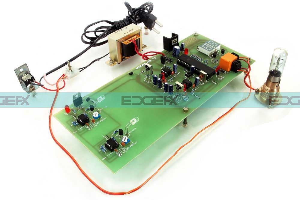  |
“OPTIMUM ENERGY MANAGEMENT SYSTEM”
CHAPTER-I
INTRODUCTION
The project is designed to monitor the number of persons entering as well as exiting a room. Electrical loads are switched ON as the first person enters and switches OFF when the last person leaves. IR sensors used in combination with microcontroller to monitor all the operation. This helps in saving lot of energy.There are two pair sensors, each kept at certain distance from the other. One pair of sensor consists of transmitter and a receiver, kept exactly opposite to each other. The transmitting part emits modulated IR light which is received at the receiver end and fed to a microcontroller of 8051 family.When a person enters the room then microcontroller senses it (with the help of IR sensors) and increment the count and displays it on 7 Segment display and also switches ON the load. In the same way when a person exits the room, the lamp is OFF. The 555 timer driven 38 KHz signal from IR LED gets interrupted on to the IR receiver to sense the person entering as well as exiting which is fed to a 555 timer. The output of 555 timers is fed to the Microcontroller for analyzing and control purpose. The load operation is handled by a relay interfaced to the microcontroller.Further the project can be enhanced by using timer arrangement in the project, so that if the load switching doesn’t take place for some reason as desired, then timer would complete the task after prefixed time.
ELECTRONIC COMPONENTS DESCRIPTIONS
4.2ALTERNATING CURRENT:
Alternating current (AC), is an electric current which periodically reverses direction, whereas direct current (DC, also dc) flows only in one direction. Alternating current is the form in which electric power is delivered to businesses and residences, and it is the form of electric energy that consumers typically use when they plug kitchen appliances, televisions and electric lamps into a wall socket. A common source of DC power is a battery cell in a flashlight. The abbreviations AC and DC are often used to mean simply alternating and direct, as when they modify current or voltage. The usual waveform of alternating current in most electric power circuits is a sine wave. In certain applications, different waveforms are used, such as triangular or square waves. Audio and radio signals carried on electrical wires are also examples of alternating current. These types of alternating current carry information encoded (or modulated) onto the AC signal, such as sound (audio) or images (video). These currents typically alternate at higher frequencies than those used in power transmission. A.C generator consist of a rectangular coil in a magnetic field. The two end of the loop are connected to slip rings and they are in contact with two brushes. Consider the rectangular coil rotating in the magnetic field and it produce the voltage which constantly changes in amplitude and direction. A direction of the induced voltage depend on the direction of moment of the coil. It is shown in the alternating current or voltage is represented by a vector rotating in counter clockwise direction with the same frequency as that of alternating quantity. Also the length of the vector projection should be equal to maximum value of alternating quantity. This vector representation of alternating quantities simplify the complexity of the problem in the a.c circuits
4.3 TRANSFORMER:
A transformer static electromagnetic device by means of which electric power in one circuit is transformed into electric power of the same frequency in another circuit. Transformer can increase or decrease the voltage in a circuit with a corresponding decrease or increase in current.
PRINCIPLE OF OPERATION:
The principle of operation of transformer is based on faraday’s laws of electromagnetic induction. When never flux linked with a coil change an emf is induced in the coil and this given by
E=dØ/dt
A transformer consist of two types of windings called primary winding (P) and secondary winding(S), which are mutually coupled through an iron core. When the primary winding is excited by an A.C supply, An alternating flux links with the secondary winding to induce an emf in it.
4.4 RECTIFIER:
Rectifier is a device which converters A.C voltage unidirectional voltage PN junction diode are used for rectification purpose the different type of rectification are
1. Half wave rectifier
2. Full wave rectifier
3. Bridge wave rectifier
HALF WAVE RECTIFIER:
The rectifier conducts only during the positive half cycle of input ac voltage during the negative half cycles no voltage appears across the load the circuit diagram is shown
It is seen that the diode is forward biased during the positive half cycle conducts. During negative half cycle, the diode is reverse biased and thus not conduct. Therefore current flow in the circuit only for the half-cycle and those DC O/P is obtain across RL.
DISADVANTAGE OF HALF-WAVE RECTIFIER
1)Power is supplied only all cycles, therefore output is low
2)Therefore output appears only for all cycles filtering becomes complex
FULL WAVE RECTIFIER
In the full wave rectifier voltage appears across the rectifier for both the positive and negative half wave rectifier of the voltage.
Two diode are made use of one diode during the positive half cycles and the other diode contact during the negative half cycle.
DISADVANDAGES OF FORWARD CENTER TAPPED RECTIFIER
1) It is difficult to locate the Centre tap on the secondary winding.
2) Diodes must have high PIV.
3) Each diodes uses only one half cycles of the transformer secondary voltage, therefore dc output is small.
BRIDGE RECTIFIER
The need for center tapped transformer is eliminated in a bridge rectifier. The bridge rectifier provides output voltage for both positive and negative cycle.
It has 4 diodes connected to form a bridge. The input voltage is applied across diagonally opposite ends of the bridge.
During the positive half cycles diodes D2 and D4 are formed biased and conduct, where as D1 and D3 are reserved biased. For negative half cycles d1 and d3 conduct. The current though R1 flows in the same direction for both positive and negative half cycles, therefore a dc voltage is obtained across RL.
The average and vrms values are same as that of centered tapped full wave rectifier therefore efficiency is 81.2%and ripple factor 0.48 piv of each diode is Vm.
ADVANTAGES OF BRIDGE RECTIFIER
1. These is no need for center tapped transformer.
2. The PIV across each diode VSM
3. The output is twice that of center tapped rectifier.
4. The TUF is high.
DISADVANTAGE OF BRIDGE RECTIFIER
It requires four diodes.
4.5 FILTER:
A filter circuit is a device to remove the A.C components of the rectified output, but allows the D.C components to reach the load. A filter circuit is in general a combination of inductor (L) andCapacitor (C) called LC filter circuit. A capacitor allows A.C only and inductor allows D.C only to pass.
TYPES OF FILTER CIRCUITS:
1) Capacitor filter.
2) Choke input filter
3) Capacitor input filter
4.6 VOLTAGE REGULATOR:
7805
Generally a rectifier is required to produce pure DC supply for using at various places in the electronics circuits. However the output of a rectifier has pulsating character. it contain AC and DC Components . the AC component is undesirable and must be kept away from the load. To do so, a filter circuit is used which removes the AC component and allows only the DC component to reach the load.
A filter circuit is a device which removes the AC component of rectifier output but allows the DC component to reach the load.
78xx (sometimes L78xx, LM78xx, MC78xx...) is a family of self-contained fixed linear voltage regulator integrated circuits. The 78xx family is commonly used in electronic circuits requiring a regulated power supply due to their ease-of-use and low cost.
4.7 DRIVER CIRCUIT:
In electronics, a driver is an electrical circuit or other electronic component used to control another circuit or component, such as a high-power transistor, liquid crystal display (LCD), and numerous others.
They are usually used to regulate current flowing through a circuit or to control other factors such as other components, some devices in the circuit. The term is often used, for example, for a specialized integrated circuit that controls high-power switches in switched-mode power converters. An amplifier can also be considered a driver for loudspeakers, or a constant voltage circuit that keeps an attached component operating within a broad range of input voltages.
Typically the driver stage(s) of a circuit requires different characteristics to other circuit stages. For example in a transistor power amplifier, typically the driver circuit requires current gain, often the ability to discharge the following transistor bases rapidly, and low output impedance to avoid or minimize distortion.
4.8 RESISTOR:
A resistor is an electrical component that limits or regulates the flow of electrical current in an electronic circuit. Resistors can also be used to provide a specific voltage for an active device such as a transistor.
4.9 INDUCTOR:
An inductor, also called a coil or reactor, is a passivetwo-terminalelectrical component that stores electrical energy in a magnetic field when electric current is flowing through it.[1] An inductor typically consists of an electric conductor, such as a wire, that is wound into a coil.
4.10 CAPACITOR:
A capacitor is a passivetwo-terminalelectrical component that stores electrical energy in an electric field. The effect of a capacitor is known as capacitance. While capacitance exists between any two electrical conductors of a circuit in sufficiently close proximity, a capacitor is specifically designed to provide and enhance this effect for a variety of practical applications by consideration of size, shape, and positioning of closely spaced conductors, and the intervening dielectric material. A capacitor was therefore historically first known as an electric condenser
4.11 DIODE:
Diode is extensively used to convert to AC to DC. It acts as rectifier. The diode allows the current in only one direction. When the positive supply is give to the diode gets forward based. Suddenly the diode will be conducts when the negative supply is given to the diode gets reversed based suddenly the diode will diode not be conducts.
APPLICATION:
a) They are used as rectifier elements in DC power supplies.
b) They are used as a signal in communication circuits for modulation and demodulation.
c) They are used in clipper and clamper circuits.
d) They are as a switch in logic circuit used in computers.
4.2 MICROCONTROLLER:
INTRODUCTION TO TARGET PROCESSOR AT89C52:
Functioning of AT89C52:
The AT89C52 is a low-power, high-performance CMOS 8-bit microcomputer with 8Kbytes of Flash programmable and erasable read only memory (PEROM). The device is manufactured using Atmel’s high density nonvolatile memory technology and is compatible with the industry standard 80C51 and 80C52instruction set and pin out. The on-chip Flash allows the program memory to be reprogrammed in-system or by a conventional nonvolatile memory programmer. By combining a versatile 8-bit CPU with Flash on a monolithic chip, the Atmel AT89C52 is a powerful microcomputer which provides a highly flexible and cost effective solution to many embedded control applications.
LED refers to the light emitting diode. It is a forward biased PN junction, which emits light when energized. When the bias is applied, the electrons and holes move towards the junction and recombination takes place. As a result of recombination, the electrons lying in the conduction bands of N- region fall into the holes lying in valence band of a P- region.( The difference in energy is emitted in form of light for GaAsP – Gallium arsenide, GaP – Gal-lium phosphide, GaAsP – Gallium arsenic phosphide).
Multi-color LEDs:
A LED that emits one color when forward biased and another color when reverse biased is called a multicolor LED. As a power indicator. A LED can be indicate whenever the power is ON or not.
Advantages of LED:
The light emitting diode (LED) is solid state light source. LEDs have replaced incandescent lamp in many applications because they have the following advantages.
1) Low voltage
2) Longer Life (more than 20 year)
Applications:
1) In 7-segment, 16-segment and dot matrix displays. Such displays are used indicates alphanumeric characters and symbols in various systems such as digitals clocks, microwave ovens.
2) Stereo tuners, Calculators.
3) For indicating power ON/OFF conditions, power level indicators of stereo amplifier.
4) In optical switching applications.
4.3.1SEVEN SEGMENT DISPLAY LED:
LEDs arranges in segments is called 7-segment display.LEDs are so arranged, to display the character. They are named a through G. Each LEDs from the part of character displayed.
1) Common anode type
2) Common cathode type
4.4 INFRARED SENSOR
An infrared sensor is an electronic instrument which is used to sense certain characteristics of its surroundings by either emitting and/or detecting infrared radiation. Infrared sensors are also capable of measuring the heat being emitted by an object and detecting motion.
IR Transmitter and receiver are used to control any device wirelessly, means remotely. TV remote and TV are the best example of IR transmitter and receiver. TV generally consist TSOP1738 as the IR receiver, which senses modulated IR pulses and convert them into electrical signal. Here in our circuit we are building IR remote and its receiver. We are using IR LED as transmitter and TSOP1738 as IR receiver.
4.4.1IR LEDs:
IR LED emits infrared light, means it emits light in the range of Infrared frequency. We cannot see Infrared light through our eyes, they are invisible to human eyes. The wavelength of Infrared (700nm – 1mm) is just beyond the normal visible light. Everything which produce heat, emits infrared like our human body. Infrared have the same properties as visible light, like it can be focused, reflected and polarized like visible light.
Other than emitting invisible infrared light, IR LED looks like a normal LED and also operates like a normal LED, means it consumes 20mA current and 3vots power. IR LEDs have light emitting angle of approx. 20-60 degree and range of approx. few centimeters to several feet, it depends upon the type of IR transmitter and the manufacturer. Some transmitters have the range in kilometers.
4.4.2IR Receiver (TSOP1738):
TSOP17XX receives the modulated Infrared waves and changes its output. TSOP is available in many frequency ranges like TSOP1730, TSOP1738, TSOP1740 etc. Last two digits represent the frequency (in Khz) of modulated IR rays, on which TSOP responds. Like for example TSOP1738 reacts when it receives the IR radiation modulated at 38Khz.
Means it detects the IR which is switching On and Off at the rate of 38Khz. TSOP’s output is active low, means its output is remains HIGH when there is no IR, and becomes low when it detects IR radiation. TSOP operates on particular frequency so that other IRs in the environment can’t interfere, except the modulated IR of particular frequency. It has three pins, Ground, Vs (power), and OUTPUT PIN.
4.4.3TRANSISTOR:
CONSTRUCTION:
The BJT is made up of silicon or germanium crystal in which a thin layer of silicon sandwiched between two layer of P-type material is same PNP transistor alternatively in a NPN type material the two types of the BJT are represented on circuit symbols for on PNP and NPN transistor are shown
|
|
|
APPLICATION:
· It is used as an amplifier.
· It is used as a switch.
· It is used as an oscillator.
· It is used as a buffer.
· It is used in logic circuits.
ADVANTAGES:
· No heater or filament is required. Hence no heating delays and heating power is no needed.
· Require very low operating voltage.
· They are much smaller in size and are light in weight.
· They consume little power, resulting in circuit efficiency.
· They have long life with essentially no ageing effect.
· They are essentially shock-proof
4.4.4BC547 TRANSISTOR:
The BC547 transistor is an NPN Epitaxial Silicon Transistor. It is a general-purpose transistor in small plastic packages.It is used in general-purpose switching and amplification BC847/BC547 series 45 V, 100 mA NPN general-purpose transistors. Whenever base is high, then current starts flowing through base and emitter and after that only current will pass from collector to emitter.
4.4.5RELAY:
A Relay is nothing but a switch mostly switches are manually operated type. But the operations has not sufficient in ON and OFF purpose, it has many problems.
So we are used automatically operated switches it is worked based on the voltage across the relay coil, an relay consist of an relay coil one pole two contact the pole is a movable one. It is moved to new position by means of voltage is applied to the relay coil. The pole is normally closed and another contact is normally opened contact.
The supply is available across the relay coil, then the normally opened contact is closed and normally closed contact opened. The above explanations are suitable for single pole and double through relay. The contacts are used to following of the current.
The various current ratings are available. The current rating is not available in the market then we are assuming the total current. But the relays are not used in very high current s rating. Because of arcing at the time of contacts is opened. The relay contacts are periodically checkup is required. The operations will not be followed. So the contact is damaged on the continuous condition may gets damaged the contact, due to the heat.
The most common types of relays used in ATE applications are:
· Electromechanical Relays
· Reed Relays
· Solid State Relays (SSRs)
· FET Switches
· Electromechanical Relays
· Reed Relays
· Solid State Relays (SSRs)
· FET Switches
SOFTWARE TOOLS
5.1 VERSION DETAILS:
DEVELOPMENT TOOLS
Having a programming language is usually not enough to develop a program for a microcontroller. Some way of debugging your program is needed. I am only too painfully aware of this fact.
SIMULATORS
A simulator runs your microcontroller program on a host machine (such as your PC). You can step through the code to see exactly what is happening as the program runs. Contents of registers or variables can be altered to change the way the program runs. Eliminates (or at least delays ) the erase /burn /program EPROM cycle common in microcontroller program development.
You can work out ideas or learn about microcontrollers by experimenting with small code fragments and watching on the screen what happens. A simulator can't support real interrupts or devices, and usually runs much slower than the real device the program is intended for.
Some manufacturers have a cross between a software simulator and the hardware emulator - a hardware simulator. This is a piece of equipment that plugs into your target, and the pins will toggle and react like they should - just MUCH slower. Cost of a device like this is only about $100. Two such boards by National Semiconductor and Philips are detailed in section 6.2.
RESIDENT DEBUGGER
A resident debugger runs your program on the microcontroller itself, while showing the progress on your host machine (such as a PC). Have many of the same advantages as simulator above, with the additional benefit of seeing how the program runs on the real target machine.
A resident debugger needs to "steal" some resources from the target machine, including: a communications port to communicate with the host, an interrupt to handle single stepping, and a certain amount of memory for the resident part (on the target) of the debugger.
EMULATORS
If you've got the money, this is the equipment you want to develop your system with (yeah, that's right, a preposition at the end of a sentence!). A [usually] expensive piece of hardware that even for the cheaper versions will run you at least $700. An emulator is a sophisticated device that pretends that it is the microprocessor itself, while at the same time capturing information.
It provides full and total control over your target, while at the same time not requiring any resources from the target. The emulator can either be a standalone device with its own display, or it can be interface to a PC.
APPLICATIONS
In addition to the above home monitoring system, embedded processors and microcontrollers are frequently found in: appliances (microwave oven, refrigerators, television and VCRs, stereos), computers and computer equipment (laser printers, modems, disk drives), automobiles (engine control, diagnostics, climate control), environmental control (greenhouse, factory, home), instrumentation, aerospace, and thousands of other uses. In many items, more than one processor can be found. Microcontrollers are typically used where processing power isn't so important. Although some of you out there might find a microwave oven controlled by a Unix system an attractive idea, controlling a microwave oven is easily accomplished with the smallest of microcontrollers. On the other hand, if you're putting together a cruise missile to solve the problem of your neighbor’s dog barking at 3 in the morning, you'll probably need to use processors with a bit more computing power.
Embedded processors and microcontrollers are used extensively in robotics. In this application, many specific tasks might be distributed among a large number of controllers in one system.
Communications between each controller and a central, possibly more powerful controller.
PCB BOARD DESIGN (TRAX MAKER):
PCB
· Printed Circuit Boards are primarily an insulating material used as base, into which conductive strips are printed.
· The base material is generally fiberglass, and the conductive connections are generally copper and are made through an etching process.
· The main PCB board is called the motherboard; the smaller attachment PCB boards are called daughter boards or daughter cards.
PCB BOARD DESIGN
PCB board design defines the electrical pathways between components.
It is derived from a schematic representation of the circuit.
When it is derived, or imported from a schematic design, it translates the schematic symbols and libraries into physical components and Connections.
MANUFACTURING PROCESS
Step 1: Film Generation the film is generated from the design files (gerber files) which are sent to the manufacturing house. One film is generated per layer.
Step 2: Raw Material Industry standard 0.059” thick, copper clad panel.
Step 3: Drill Holes Using NC machines and carbide drills to drill holes according to the drill spec sent to the manufacturing house.
Step 4: Electro less Copper Apply thin copper deposit in hole barrels.
Step 5: Apply Image Apply photosensitive dry film to panel and use a light source and the film to expose the panel.
Step 6: Pattern Plate Electrochemical process to build copper in the holes and on the trace areas. Apply tin to surface.
Step 7: Strip and Etch Remove the dry film, and then etch the exposed copper. The tin protects the copper circuitry from being etched away.
Step 8: Solder Mask Apply a solder mask area to the entire board with the exception of solder pads.
Step 9: Solder Coat Apply solder to pads by immersing into tank of solder. Hot air knives level the solder when removed from the tank.
Step 10: Nomenclature Apply white letter markings using screen printing process.
STARTING A NEW PCB
· First create a Mechanical outline for the board by using one of the Mechanical Layers.
· Then create an electrical outline of the board by placing a Keep out Layer.
· The Keep out Layer aids the CAD system in automatically placing and routing of the components. Generally the Keep out Layer and the Mechanical Layer are one and the same.
IMPLEMENTATION & TESTING
· Take a bare PCB board and an ohmmeter, and ohm out the power and ground signals. If they are shorted, the Test of Futility has been completed and you have a useless board!
· Needless to say, do not plug it in. This can be caused by manufacturing errors, or by corrupt gerber files which were sent to the PCB house.
TRAX MAKER
Trax Maker is software that is used for designing the PCB board in the system. Trax Maker generates through hole and SMD (surface mount technology) designs of up to six signal layers, plus power and ground planes, silk screen overlays and solder and paste masks. Board size can be as large as 32inches (or 81cm) square. Placement accuracy is to 1mil (.001 inch or .025mm). A metric\imperial grid system allows you to work accurately in both measurement systems and the grid can be “toggled” between metric and imperial modes as you design.. The number of components you can include in your design is limited only by the memory of the computer.
BUILDING A TRAXMAKER PCB DESIGN IS A STRAIGHTFORWARD PROCESS OF:
· Defining the physical outline of the PCB.
· Selecting and placing the required component patterns from a component library. Or, if working from a schematic net list, importing and placing (manually or with the auto placement feature) the component onto the predefined board.
· Connecting the component pads with tracks, manually with the auto router, or a combination of manual and automatic track routing.
· Checking your work using TraxMaker’s built in design rules check tool.
· Printing, plotting or outputting the required manufacturing artwork or files.
· Check Gerber files using Gerber viewer/editor.
Traxmaker stores each design as a series of layers which correspond in a general sense, to the layers that make up an actual print circuit board. For ex, the top overlay layer is used to produce a top layer silkscreen with components outlines and text. Various other layers includes middle layer, mid layer, bottom layer, top overlay, bottom overlay, ground plane, power plane, board layer, keep out layer, multilayer for varying purposes.
Trax maker provides special features that address the unique requirements of PCB artwork, such as the ability to edit and print or plot the individual layers that correspond to the manufactured board.
ADVANTAGES AND APPLICATIONS
ADVANTAGES:
· Highly reliable.
· Acts fast without any delay.
· Very convenient and comfortable to use.
· Light control increase comfort and may improve productivity.
APPLICATIONS:


Comments
Post a Comment